Two transducers on the outside of a pipe, a pulse of ultrasound, and a time difference measured in nanoseconds. Understand the equation and you understand every way a clamp-on meter can lie to you.
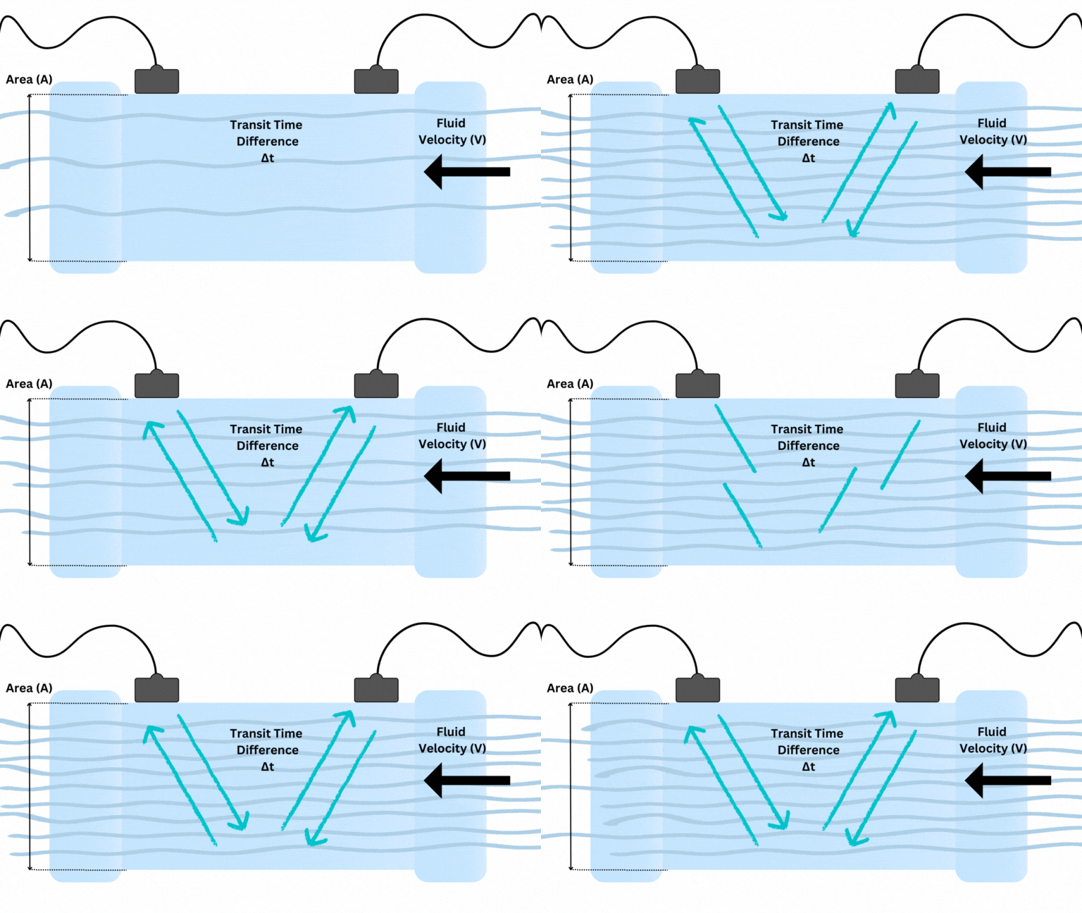
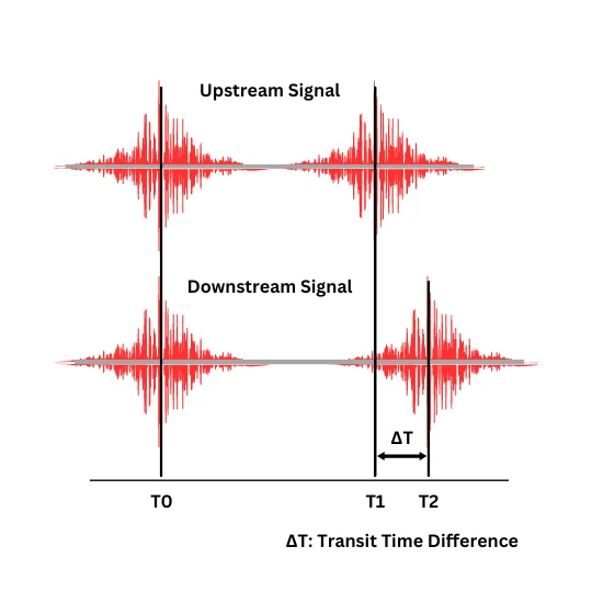
Two ultrasonic transducers are clamped to the outside of the pipe, offset along its length. Each one alternates between transmitting and receiving. A pulse fired from the upstream transducer travels diagonally through the pipe wall, through the fluid, and up to the downstream transducer — and it is carried along by the moving liquid, so it arrives sooner. A pulse fired the other way is fighting the flow, so it takes longer.
Call those two travel times tdown and tup. The difference between them — Δt — is directly proportional to the average velocity of the fluid along the acoustic path. No flow, no difference. Fast flow, big difference.
The instrument then computes volumetric flow: Q = v × A. Velocity times the cross-sectional area of the pipe.
v is the velocity on the acoustic path, and the meter assumes it can infer the mean velocity of the whole pipe from it. That assumption requires a fully developed, symmetric flow profile — which is what straight run buys you.
A is not measured. It is computed from the pipe dimensions you typed in. Get the wall thickness wrong and every reading is systematically wrong, displayed to four decimal places, with total confidence.
Sound travels through water at roughly 1,480 m/s. A liquid in a pipe is moving at perhaps 1–3 m/s. Across a 6-inch pipe, the difference in travel time between the upstream and downstream pulse is on the order of nanoseconds.
That is why digital signal processing matters, and why the good instruments talk about it. The measurement is a tiny difference between two large numbers, and every source of noise — electrical, acoustic, thermal — is competing with it. The DSP is not a feature bullet. It is what makes the measurement possible at all.
There are two ways to arrange the transducers, and the choice is not cosmetic.
Reflect mode (V-path). Both transducers on the same side of the pipe. The pulse crosses the fluid, bounces off the far wall, and comes back. The signal travels through the fluid twice, which doubles the path length and therefore doubles Δt — more signal to work with. It is also far easier to install, because you only need access to one side of the pipe. This is the default, and it is the right default.
Diagonal mode (Z-path). Transducers on opposite sides, diagonally offset. The pulse crosses the fluid once. Half the path length, so half the Δt — but also half the attenuation. Use it when the signal is struggling: thick-walled pipe, very large pipe, acoustically difficult material, or a fluid that attenuates heavily.
Rule of thumb: start in reflect mode. If the signal is weak, go diagonal. If diagonal does not fix it, the problem is the pipe, not the mode.
Doppler does not time anything. It fires a continuous ultrasonic signal into the fluid and listens for what bounces back off particles and bubbles being carried along in the flow. Because those reflectors are moving, the returned signal comes back at a shifted frequency — the same effect that raises the pitch of an approaching siren and drops it as it passes.
The size of the frequency shift is proportional to the velocity of the reflectors, and the reflectors are moving with the fluid. So measuring the shift measures the flow.
This inverts the requirement. Transit-time needs the fluid to be acoustically clear so the pulse gets through. Doppler needs the fluid to be dirty so there is something to reflect off. Put a Doppler meter on clean potable water and it reads nothing at all — not badly, nothing. Put a transit-time meter on sludge and the signal scatters and it drops out.
The full comparison, including where the boundary actually sits →
Look at Q = v × A once more. The meter takes A from the pipe dimensions you entered. If the pipe is only half full, the actual flowing area is half of what the meter thinks it is — and the meter has no way of knowing.
So it reports roughly double the real flow. Confidently. With no error flag. This is the single most dangerous failure mode in clamp-on measurement, because the number looks entirely reasonable.
If your pipe is not reliably full — a gravity sewer, a discharge that breaks the surface, a line with a high point that traps air — you do not need a clamp-on flow meter. You need an area velocity meter, which measures depth and velocity and computes the real wetted area. We will tell you that rather than sell you the wrong instrument.
Between the face of the transducer and the pipe wall there is a microscopically thin film of air. Ultrasound crossing from a solid into air and back into a solid loses almost all of its energy at each boundary — the acoustic impedance mismatch is enormous. A thin layer of air is, acoustically, a wall.
Couplant — a viscous gel or grease — displaces that air and provides a continuous acoustic path from transducer to steel. That is its whole job, and it is why a perfectly good instrument with insufficient couplant reads nothing.
It also explains the classic problem pipe: cement-mortar-lined ductile iron. If the mortar has delaminated from the pipe wall, there is an air gap inside the pipe that you cannot reach and cannot fill. The signal stops there.
Send us the pipe material, wall thickness, lining, and fluid. We will tell you honestly whether a clamp-on meter can read it — before you spend anything.
Request a quote